First of all, please follow below instructions to make required modifications to your mainboard (click on your mainboard name near “+” to get additional details).
Our LVDS PCB is connected through two Parallel LCD Expansion Headers on the bottom side of mainboard. They are:
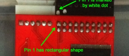
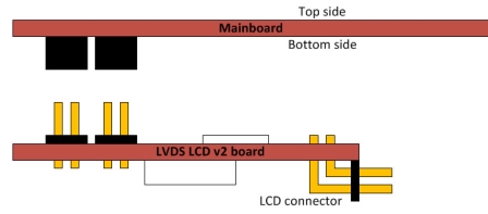
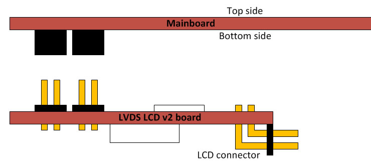
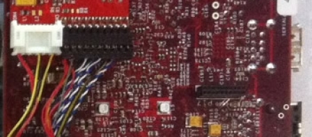
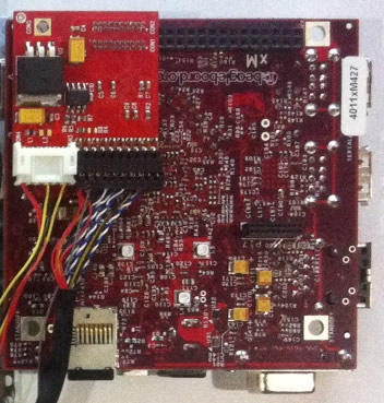
Connect LCD data and power connectors to LVDS PCB v2 like on drawing 1. Pin 1 is marked by white dot on data connector, and has rectangular shape on PCB. Power connector has key and can’t be inserted wrongly. Place PCB v2 to your mainboard. Please, pay attention that LCD and power connector on our PCB should be pointed toward center of motherboard (click drawing 2). You should get connection like on drawing 3 (BeagleBoard-xM is shown).


© 2011-2023 Chalkboard Electronics ® All rights reserved.
Awesome example – I connected to my BeagleBoard xM and started it up with the LCD in one attempt – perfect!
Hi,
The BB xM example picture looks like the adapter board is covering the edge of the main expansion connector, would this prevent connecting a pin header to the connector? The pins at the lcd connector end of the expansion connector are the ground pins and vital for expansion card operation
Hello Tommi,
This photo is made slightly under angle. Actually, you have direct access to these pins on expansion headers.
You can download gerbers and check it yourself.
Hello,
I just want to double check if the PCB board connection for Pandaboard ES is right.
Are the following connection combinations correct?
CON1 (PCB) -> J4 (LCD Connector A)
CON2 (PCB) -> J1 (LCD Connector B)
Also, in order to place the PCB board, a rubber footing needs to be removed. Is it the way supposed to be?
Thanks,
panda
Hello panda,
Yes, you are correct.
For rubber footing – you can just move it to another place close to our PCB in order to keep board steady on 4 foots.
to avoid confusion due to typos: at least on my Pandaboard ES J4 is labeled Connector *B* and J1 is labeled *A*, so (at least for me) this should read
CON1 (PCB) -> J4 (LCD Connector B)
CON2 (PCB) -> J1 (LCD Connector A)
Thanks,
Harald
Hi guys,
Need to double confirm,
Do we need to take out the Resistor for Panda ES version?
Then about the board is it connected to the bottom of the panda ES or the top?
from pandaes, reply it is bottom and it will be blocked my the rubber padding of PandaES board.
My PandaBoard ES is revision B.
Hello Dennis,
You don’t have to remove/solder resistors for Panda ES – just install headers.
Board is connected on bottom side. Rubber padding can be shifted to different location on board (it has glue surface).
Dr. Ace,
Thanks! 😀
there is another cable which is usb type, what is that for? is that needed?
that’s for the touch screen…
Everything is working with my Pandaboard ES but the screen is very dark, as if the backlight was too dim. The ambient light sensor is working (if I block it the screen gets even dimmer) but it´s not confortable to read. How can I increase the backlight power? Thanks
Hello Daniel,
Try tips from this blog post: https://www.chalk-elec.com/?p=1391
Hi Dr. Ace,
I am using Ginger Bread pre-build for Beagleboard XM
http://software-dl.ti.com/dsps/dsps_public_sw/sdo_tii/TI_Android_DevKit/TI_Android_GingerBread_2_3_4_DevKit_2_1/index_FDS.html
It could display on the screen, but touch screen does not work, back light seems does not work too (nothing changed under lighting change at ambient sensor).
Any advices?
Thanks,
Taddy.
Hello Taddy,
You should recompile kernel to include Multi-touch HID driver to get touchscreen working.
As to backlight – please check that your sensor wires are not damaged. Alternatively, you can follow this tip for manual backlight control: https://www.chalk-elec.com/?p=1391
Hello
Any plans for the next Assembled PCB ver(3) to fit exactly below the pandaboard?
(shifting the power and LDC connector, the Microchip microcontroller, SPX1567 to the left)
In that case we could use cases like: https://specialcomp.com/pandaboard/order.htm
Thanks
We designed board as small as possible to fit right under Panda. the only parts getting out of Panda are LCD/backlight connectors.
Actually there are around 3mm in the SPX1567 / power connector side that are off . Just below the pandaboIn your next design you could shift the entire PCB tracks to the conn 1 & 2 side.
Best regards
PS: It is not critical, I used a dremel to remove part of the acrylic box, but will be nicer.
Ok, I got what you mean. Unfortunately we can’t shift entire PCB design to the side, because it will overlap I/O extension connectors on Panda. The only way would be to change CON4 to smaller pitch one.
I bought a LVDS LCD interface board Ver 2 for Beagleboard Xm and tried to connect it Innolux 10 inch LCD, but I couldn’t get any success.When I look at the connections I saw that RX3+ at header-10×2 pin 20 was connected to GND.Is that normal?Also when I connect it I see only backlights and black screen. Do I need to set bootargs? Do I need to change PIC firmware that includes my LCD’s data?
You should provide datasheet of your LCD to get support. Email to support@chalk-elec.com
Yes, it is fully compatible with PQ 3Qi-01.
PQ101WX01 should be OK as well.
We still negotiate with Element14.
Ciao Dr. Ace, I’m very tempted to buy a couple of boards for IGEPV2, could you also provide LVDS cables assembled for PQ 3Qi-01 ?
Marco, please drop your request to sales@chalk-elec.com with exact qty, they will provide custom invoice to you.
It is impossible to solder it wrong way, because our board has mounting hole that should match the hole on IGEPv2.
I have 30 Pin LVDS 6-bit (18-bit total RGB) LCD Panel (LG LB070WV8). Will this panel work with the PCB v2? Do you have a different cable that will work with this 30 pin LCD module (rather than the 40 pin module you use in your kit)?
Thanks,
Ian
Yes, it will work. You have to ask your LCD supplier for LVDS cable. We make custom cables for our LCDs, and unfortunately can’t supply cables for third-party panels.
Usually, our sales team answers in 1-2 days.