Archive for blog
LCD holder for RaspberryPi and Beaglebone Black
Well, today is Monday, and here is our last release - LCD holder
We design all of our new video converter boards with all components on top side only. As a result, flat bottom side allows to stick board on back side of LCD, like we did for our new 7"/10" integrated platforms, and just released dualLVDS converter. But what about main board, like RaspberryPi, Beaglebone, etc? They have components on both sides and we are forced to place them right on table or look for enclosure. That's why we made LCD holder for these boards - simple board with low profile metal standoffs and flat bottom side.
Here is Beaglebone Black mounted on LCD holder:
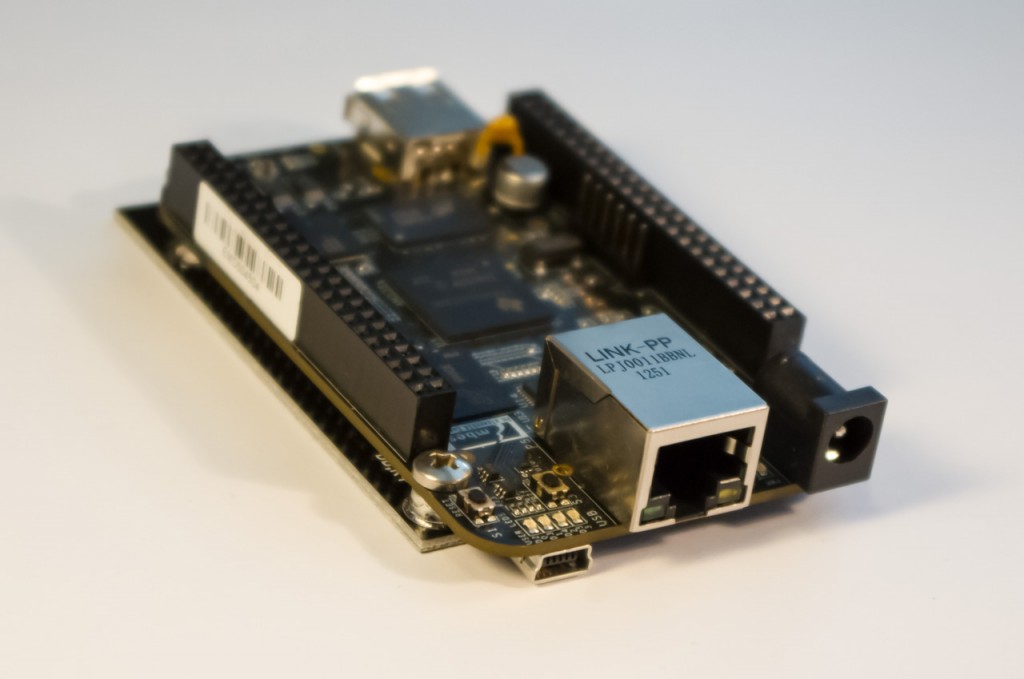
Board height is increased just a little bit (less than 1 mm in this case measuring from mini-USB connector on bottom side of Beaglebone), but now it has flat surface and can be fixed on bottom side of LCD with double-sided glue tape, providing fully integrated solution for your projects.
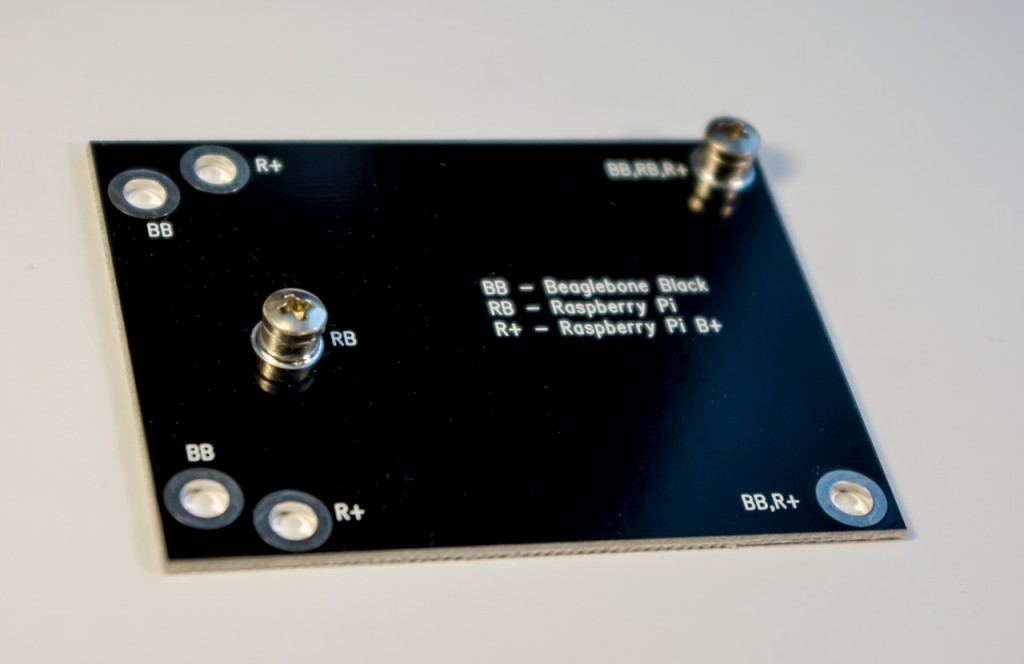
LCD holder has holes for RaspberryPi, RaspberryPi B+, and Beaglebone Black:
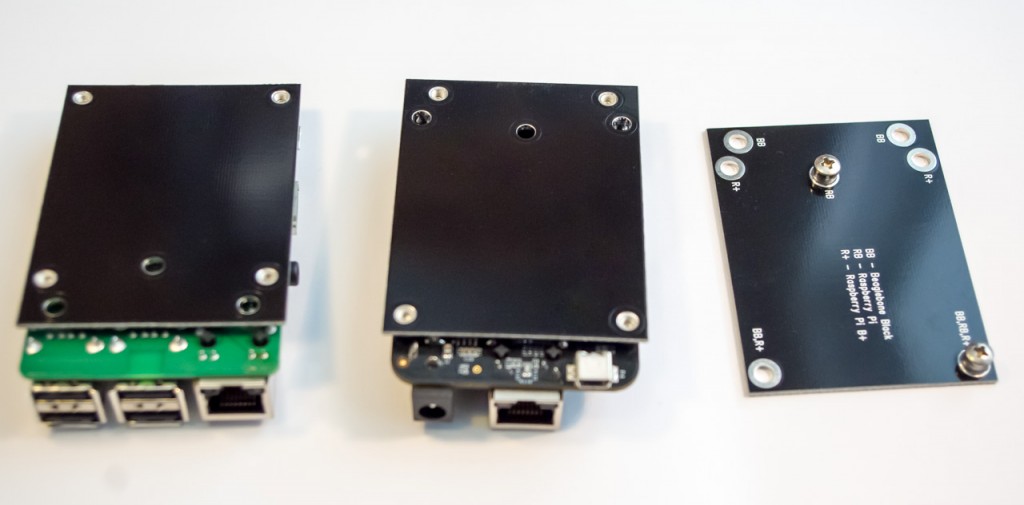
We are going to offer this board as an accessory for our new LCD bundles, and you will be able to select holder for your mainboard.
Each board will be supplied with mounting screws
New integrated 10-inch platform
Lets continue with our product releases. Here is our new 10" integrated multi-touch platform:
- 10" black frame capacitive multi-touch LCD panel with IPS technology
- 1366x768 native resolution, high brightness (450 cd/m2) and contrast (800 CR)
- capacitive multi-touch panel with up to 10 fingers, standard Windows USB HID specification
- extra-low power consumption, can be powered by the same USB cable that used for touchscreen - check photo below
- fully integrated solution - no external boards and cables
- slim design (<9 mm thickness including electronic and connectors)
- easy installation – just connect and it will work
- mini HDMI input accepts any resolution up to 1920x1080 (FullHD) and scale down to native LCD resolution
- slim-profile power connector (OD=2.6mm, ID=0.65mm, positive central pin)
- mini USB connector for touchscreen with support for driver-less single touch, or multi-touch with additional driver
- audio engine provides decoding of HDMI stream audio and outputs it to standard 2.5mm connector
- external ambient light sensor for automatic brightness control
- internal LVDS scaler allows to get HDMI with any resolution from virtually any HDMI source, like RaspberryPi, Beagleboard/Pandaboard/, Beaglebone Black, Hackberry, Odroid, Cubox, mk802 and others Android stick clones, Gooseberry, Nitrogen/Sabre, OLinuXino-A13, normal PC/notebook, video players, etc.
New 10" integrated solution, top view
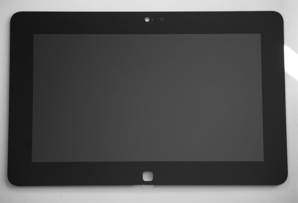
Hole in the bottom center part of frame is for the main action button, like Home button in Android or Windows. And we are going to offer capacitance sensitive button for this hole as an option. For mass qty orders we can also make it with your custom logo in silver or gold color. Button action will be available as an USB HID event for your target platform.
New 10" integrated solution, bottom view
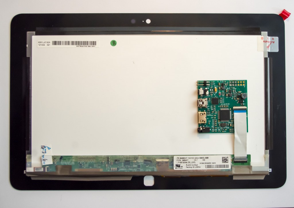
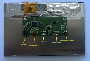
As you can see on above photo, control board has similar interfaces to 7" integrated solution - mini-USB for touchscreen and optional power, mini-HDMI for video input, power jack, audio 2.5mm jack, and input for ambient light sensor. All integrated on bottom side of LCD.
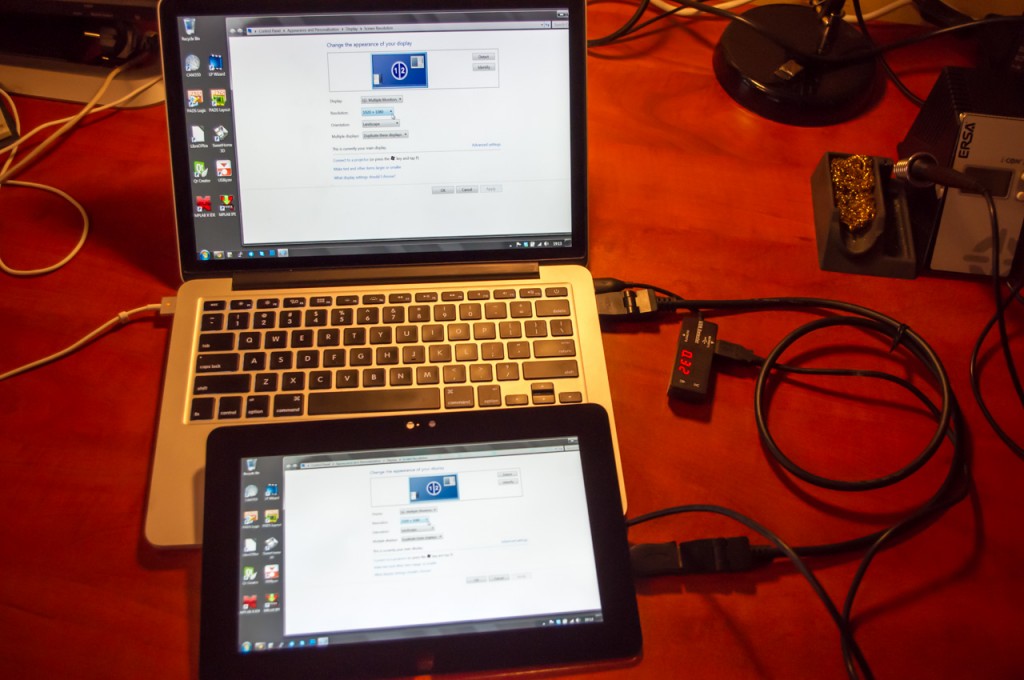
New 10" in action, connected to 1920x1080 HDMI source, powered by USB, current consumption is 320mA only!
One more new product announce will be on Monday. The same time we will announce prices and new product availability in stock.
Full HD is here
Well, let me answer all your emails at once.
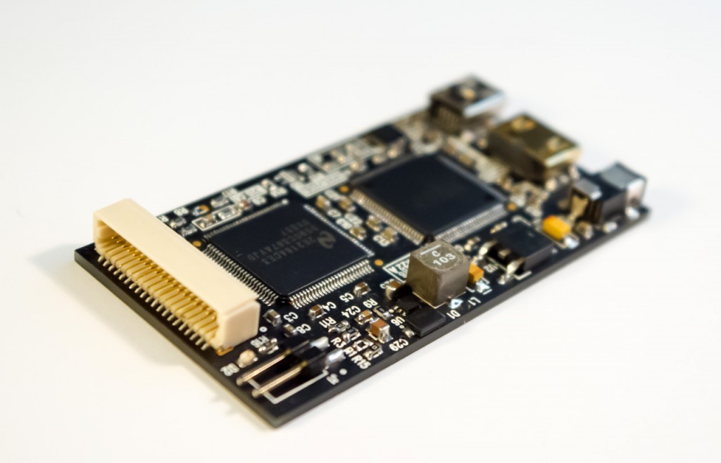
Meet our new Full HD HDMI converter:
- slim compact design - 6.5x3.5x0.7 cm only
- flat bottom side - can be fixed right on bottom side of LCD panel
- HDMI to Dual-LVDS converter for resolutions up to 1920x1200, 16M colors
- mini HDMI input for video
- slim-profile power connector (OD=2.6mm, ID=0.65mm, positive central pin)
- mini USB connector for easy firmware update, and for programmable backlight control from user application (yes, we did it!)
- integrated backlight controller can generate up to 37V/1.5A right on board for most LCDs up to 23"
- input for external ambient light sensor for automatic brightness control
- easy programmable EDID block (through USB)
- new universal 40-pins LVDS connector
New dual-LVDS HDMI converter for FullHD applications
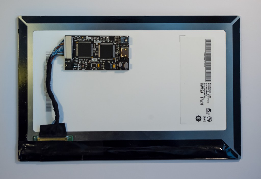
We will offer this converter as a standalone solution, and will also offer in bundle with our new FullHD+ LCD:
FullHD+ 10" LCD specifications:
- Display: 10” full-color a-Si TFT with IPS technology
- Native resolution: 1920x1200 pixels
- Aspect ratio: 16:10 (widescreen)
- Display colors: 16 millions (8-bits per color)
- Panel dimensions: 229.5mm (H) x 149.2mm (V)
- Weight: 138 grams
- Power consumption: 3W (typ)
- Brightness: 400 cd/m2 (nits)
- Contrast ratio: 800:1
- Viewing angle: 89 deg (all directions)
- Works well with RaspberryPi (original and B+), actually it's the highest possible resolution supported by RasPi
New FullHD+ 10" LCD with integrated HDMI converter
That's not all, folks! Lets continue tomorrow with news. Stay tuned!
How to program custom EDID data in HDMI converter
EDID stands for Extended Display Identification Data (EDID), and is a data structure provided by an LCD to describe its capabilities and supported resolutions to a video source (RaspberryPi, PC, Android stick, etc.) EDID is stored in EEPROM memory chip with I2C interface on LCD receiver side. In our case this is small chip U5:
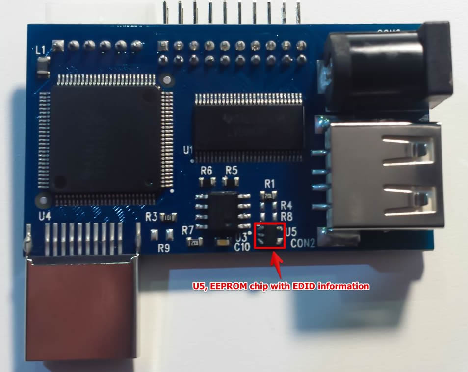

We ship our HDMI converters with pre-programmed EDID data for our standard LCD panels (1280×800 for single-LVDS, and 1920×1200 for dual-LVDS converter). If you want to use it with different LCD panel and different resolution, then you should update EDID information stored in EEPROM chip. Fortunately, this is not difficult procedure, and it will not require any special hardware tools. All you need is Linux powered PC or board (like RasPi) with HDMI output and keyboard to type in terminal commands. So, run Linux, open Terminal, connect our HDMI converter to HDMI output of PC, and power it with external power supply. Others cables are not required.
- First of all, lets install required tools. We will need Python SMBus library to read/write data to I2C bus, and EDID decode tools to represent EDID data in human-readable form:
1sudo apt-get install python-smbus edid-decode
- Then we should download edid-rw utility:
1git clone https://github.com/bulletmark/edid-rw
- And write-edid script that I wrote to simplify update process:
1git clone https://github.com/ChalkElec/write-edid
- Activate i2c-dev kernel module to get access to I2C bus:
1sudo modprobe i2c-dev
- Now we should find which I2C bus is used by our HDMI adapter. The simplest way is to try bus numbers one by one with command like:
1sudo ./edid-rw 0 | edid-decode
- In my case I found HDMI adapter on bus #3:
1sudo ./edid-rw 3 | edid-decode
I got output like this:
1
2
3
4
5
6
7
8
9
10
11
12
13
14
15
16
17
18
19
20
21
22
23
24
25
26
27
28
29
30
31
32
33
34
35
36
37
38
39
40
41Extracted contents:
header: 00 ff ff ff ff ff ff 00
serial number: 30 e4 45 03 00 00 00 00 00 15
version: 01 04
basic params: 90 16 0e 78 02
chroma info: e8 87 96 5a 55 95 28 22 51 55
established: 00 00 00
standard: 01 01 01 01 01 01 01 01 01 01 01 01 01 01 01 01
descriptor 1: 4c 1d 00 ec 50 20 18 30 40 30 57 00 d9 88 00 00 00 1b
descriptor 2: 16 12 00 80 50 20 16 30 30 20 47 00 d9 88 00 00 00 1b
descriptor 3: 00 00 00 fe 00 43 33 47 52 4e 80 31 30 31 57 58 31 0a
descriptor 4: 00 00 00 00 00 00 41 32 a8 00 00 00 00 01 01 0a 20 20
extensions: 00
checksum: 9a
Manufacturer: LGD Model 345 Serial Number 0
Made week 0 of 2011
EDID version: 1.4
Digital display
6 bits per primary color channel
Digital interface is not defined
Maximum image size: 22 cm x 14 cm
Gamma: 2.20
Supported color formats: RGB 4:4:4
First detailed timing is preferred timing
Established timings supported:
Standard timings supported:
Detailed mode: Clock 75.000 MHz, 217 mm x 136 mm
1280 1344 1392 1516 hborder 0
800 805 812 824 vborder 0
+hsync -vsync
Detailed mode: Clock 46.300 MHz, 217 mm x 136 mm
1280 1328 1360 1408 hborder 0
800 804 811 822 vborder 0
+hsync -vsync
ASCII string: C3GRN€101WX1
Manufacturer-specified data, tag 0
Checksum: 0x9a
EDID block does NOT conform to EDID 1.3!
Missing name descriptor
Missing monitor rangesI can recognize it by Manufacturer string that contains “LGD” – short code of LG Display company, and by resolutions numbers “1280” and “800” in Detailed mode string. For dualLVDS converter resolution will be 1920×1200
- Now we know I2C bus number and can program another EDID information to our HDMI adapter. But be careful to state correct bus number on the next step. Better check twice output on previous step, then check once again. If you state wrong I2C bus number, you can accidentally overwrite another I2C EEPROM with wrong data (like EDID information of main LCD panel of your notebook).
- We use the following command to update EDID with information from file edid_auo14.bin (in our case this is EDID information for our 14″ AUO panel):
1sudo ./write-edid.sh 3 edid_auo14.bin
- Let’s check that EDID has been updated:
1sudo ./edid-rw 3 | edid-decode
We should have the following output for 14″ EDID data:
1
2
3
4
5
6
7
8
9
10
11
12
13
14
15
16
17
18
19
20
21
22
23
24
25
26
27
28
29
30
31
32
33
34
35
36
37
38
39
40
41Extracted contents:
header: 00 ff ff ff ff ff ff 00
serial number: 06 af 3c 10 00 00 00 00 00 16
version: 01 04
basic params: 90 1f 11 78 02
chroma info: 10 b5 97 58 57 92 26 1e 50 54
established: 00 00 00
standard: 01 01 01 01 01 01 01 01 01 01 01 01 01 01 01 01
descriptor 1: ce 1d 56 d2 50 00 26 30 10 10 3e 00 35 ad 10 00 00 18
descriptor 2: df 13 56 d2 50 00 26 30 10 10 3e 00 35 ad 10 00 00 18
descriptor 3: 00 00 00 00 00 00 00 00 00 00 00 00 00 00 00 00 00 00
descriptor 4: 00 00 00 02 00 0c 39 cc 0d 3c 64 0f 0c 1b 6f 20 20 20
extensions: 00
checksum: 0d
Manufacturer: AUO Model 103c Serial Number 0
Made week 0 of 2012
EDID version: 1.4
Digital display
6 bits per primary color channel
Digital interface is not defined
Maximum image size: 31 cm x 17 cm
Gamma: 2.20
Supported color formats: RGB 4:4:4
First detailed timing is preferred timing
Established timings supported:
Standard timings supported:
Detailed mode: Clock 76.300 MHz, 309 mm x 173 mm
1366 1382 1398 1576 hborder 0
768 771 785 806 vborder 0
-hsync -vsync
Detailed mode: Clock 50.870 MHz, 309 mm x 173 mm
1366 1382 1398 1576 hborder 0
768 771 785 806 vborder 0
-hsync -vsync
Manufacturer-specified data, tag 0
Manufacturer-specified data, tag 2
Checksum: 0xd
EDID block does NOT conform to EDID 1.3!
Missing name descriptor
Missing monitor rangesAs you can see, Manufacturer string now contains “AUO”, and Detailed mode has resolution 1366×768, so we did everything right, and now we can use HDMI adapter with another panel (14″ AUO in our example)
Urgent update on May orders
We have to delay shipment of most May orders for around 2 weeks and ask for return selected shipped orders. The reason is non-stable (counterfeit?) power switch ICs supplied by one of our Taiwan supplier. Boards passed our standard QC tests, and we already shipped around 40 orders, when got several notes from customers about non-stable work. Additional tests made in our lab showed that problem arises when board is powered for more than 3-5 minutes – power switch gets hot and unstable. As a result, LCD backlight starts flicker. Here are steps that we did regarding this problem:
- We placed on hold shipment of ready orders. Your orders will be shipped in around 2 weeks counting from now. New ICs has been ordered and should arrive to us early next week. Then it will take several days to rework boards, make new tests, and prepare orders for shipment
- We wrote RMA emails to customers with already shipped orders that can have this problem. If you received email with RMA request, then please read it carefully, test your board/bundle for at least 10 minutes, and let us know about results. Unstable boards must be shipped back, LCD panel/cable is not required to be returned. If you didn’t received RMA email from us, then no reason to worry – your board has power switch IC from another batch, and is not affected with this problem
- Orders with DHL shipping option will be processed with priority
- If your project can’t wait 2 more weeks, then please write to us email about money refund – we will issue refunds immediately after processing your email
Expanding the borders
-
Our new 14″ touchscreen LCD with Windows 8 – multi-touch demo:
-
First run with RaspberryPi:
-
Assemby of our 4.3″ touchscreen LCD:
-
Demo run of 4.3″ touchscreen LCD with Arduino:
Company update
Hello, everyone!
It was a long time since my last post, and I had one reason for this – big business customers came to us with large orders after they found us, and we were not ready for the big show. Big qty orders, tough deadlines and everyday online technical support. It was tough challenge for us. We tried to reserve at least some of panels from each batch to refill our online web-shop and support our community, but these panels were sold in several hours, and we again got tons of emails with requests for stock.
After couple months like this we saw only one solution – to upgrade our whole SMT production line for higher grade equipment, hire additional staff, and to automate production planning and order processing tasks. We managed to find new big office for production, sign rent, and started renovation. At the same time we ordered new SMT equipment: semi-automatic stencil printer with optical alignment, high-speed PnP from Autotronik with dual heads, new oven with nitrogen process, and PCB cleaning machines. They will arrive next Tuesday. Equipment is so big and heavy, that we have to use crane to hoist to 2nd floor, and will dismantle window to move it in. Setup and calibration will take around 1 week, after that we will have high-speed production.
Also, we work to automate our process handling and shipping procedures. Our goal is to reduce time to 1-2 hours from receiving order to shipping it to you. Yes, we are working to improve all the time.
Now, lets check out several news regarding our products:
- Our current 10″ LG panel (1280×800) is obsolete (got EOL status last December). We can continue to supply it only to customers who has signed supply contract with us.
- We have new 10″ IPS panel with resolution 1366×768, black frame, 10 fingers multi-touch with USB interface. Good news is that this panel will have integrated HDMI board like our 7″, with LVDS scaler, HDMI audio extract, and USB HID touch driver. Thus, you will be able to use it hassle-free with virtually any hardware platform. No more kernel hacks, no more resolution limitations!
- We also finished design of FullHD 10″ panel with capacitive touch. It will be available for order end of February.
- Next is small-size cheap LCD solution based on FT800 chip. Welcome, Arduino and Launchpad lovers! You will get complete 4.3″ LCD with touchscreen, audio, and SPI/I2C interface.
- Finally, we are starting to offer capacitive touchscreens with USB interfaces for those who has already own LCD, and just need touch interface.
Follow us on Twitter @ChalkElec to get instant updates.
How to update firmware on our touch panels and LCD
All of our new LCD and touch panel solutions are using Microchip PIC microcontroller that controls all other components like touchscreen, HDMI receiver, LVDS scaler, etc. To update PIC firmware, we should run it in bootloader mode, and upload new firmware through USB with special HIDBootloader program. Here are the required steps:
- Download Bootload application, it is available as:
- Compiled Windows application or
- Sources for compilation on Linux and Mac OS platforms
- Disconnect our panel/LCD from power supply, then:
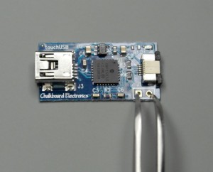
- You should see LEDs on board (D1 and D2 on 7″ LCD, and D1 on 7″ touch controller) blinking alternately. You can remove the tweezers after that
- Also, your PC should detect new device called “HID USB Bootloader” and HID bootloader software will inform that “Device attached”.
- Then you should click button 1 in software dialog, select firmware file (.hex extension), and press button 2 to upload it. Wait until software inform that “You may now unplug or reset the device”
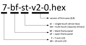
Firmware is enumerated as below. For touch-only panels and LCD-only panels you can use any version of firmware for your size LCD. In case of any technical request, please let us know version of firmware that you use
Firmware updates will be published on corresponding product pages
Update on 7inch status
UPDATE 22-Jul-2013: we finished new PCB design and made tests that were positive. New PCBs and components are ordered, we will do our best to start shipping for opened pre-orders end of next week.
Short version:
After-production tests showed that we have problems with design and need to go for one more re-design/production cycle. Therefore, we are returning money for all pre-orders, and will open sales only after the products in stock are assembled and tested.
Long version:
Last weeks we had real hell here. We assembled first batch of 12 displays and found that almost all of them have serious problem with video synchronization. Others have problems with video colors. It took a lot of time to go through all checkings and tests to figure out that problem is not with schematic, PCB, LCD, components, EMI, but with LCD side connector. Let me show you our current LCD connection – it looks like this when assembled and bonded to bottom side of LCD:
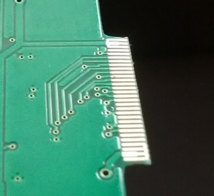
“Finger” part of PCB is used as a mate connector for LCD, it has contact pins on bottom side:
PCB thickness is 1.6 mm, thickness of this “finger” is 0.3 mm.
We ordered third-party CNC milling of “finger” part to reach required thickness. And that’s the source of problem – real thickness is 0.2-0.25 mm and it varies. As a result, some pins don’t have solid contact with LCD connector and we get problems with synchronization and colors. Its pretty clear that we have to re-design this connection part between PCB and LCD. It will take several weeks additionally.
What we are going to do:
- We will re-design connector part. Currently, we consider two approaches: rigid-flexible PCB or normal PCB with FPC connector and short (1-2 cm) FPC cable.
- We received your pre-orders several months ago, and still can’t supply product. We can’t keep you waiting anymore, therefore we decided to offer you one of following:
- we refund your money and provide $15 discount coupon for any current or future purchase in our web-shop
- alternatively, we can offer our current 10″ bundle as a substitution
- We will collect your decisions to specially created e-mail: report@chalk-elec.com – please provide your full name and order # to help identify you and your order. Next week, Monday (1st July) we will proceed to refund money by default to anyone who didn’t select any option.
- We will continue to work on 7inch integrated product, and I will publish our progress in Twitter @ChalkElec and here in blog.
- We will open stock after we get assembled and tested units.
I personally receive many emails, tweets and blog comments with requests about release date and status, and we are executing all possible approach to release it as soon as possible. We worked very hard, often stay in office till midnight, and going to continue with this routine until we get it done or turned into Zombies.


